Stop Blinking!!!!!
Il Nes è una console storica e a mio avviso fantastica!
Io lo uso tutt'oggi nonostante abbia praticamente la mia età, e non mi ha mai tradito...
L'unica cosa che capita sporadicamente è il fenomeno del blinking...cioè che vi lampeggia la lucina rossa all'accensione e che quindi non vi partono i giochi.
La soluzione consiste nel sostiruire il connettore a 72 pin perchè un pò con la sporcizia e un pò con il tempo si ossida innescando malfunzionamenti nella lettura della cartuccia inserita.
Qui di seguito proverò ad illustrarvi con una piccola guida come sostituire il connettore 72 pin con uno nuovo (facilmente reperibili sulla baia ;)) e anche come pulire il connettore sulla scheda madre (se sostituite solo il connettore 72 pin fate un lavoro a metà ;) ).
The NES console is a fantastic historical and in my opinion!
I use it so far despite having almost my age, and I have never betrayed ...
The only thing that happens occasionally is the blinking problem.
The solution is to excange the old 72-pin connector with one new beacuse the old connector is dirty and maybe a bit oxidizes triggering malfunctions in the reading of the cartridge inserted.
Below I will try to explain with a little guide how to replace the 72-pin connector with one new (you can found it easily on ebay;)) and also how to clean the connector on the motherboard (if you replace the 72 pin connector only you'll do just an half job; )).
Gli oggetti necessari per questa piccola riparazione sono davvero pochi:
The necessary objects for this small repairs are very few:
- Connettore 72 pin nuovo (72 pins connector replacement)
- Cacciavite a stella (screwdriver)
- Spray apposito per contatti elettrici (electronic cleaner spray)
- Panno che non lasci peluzzi appropiate cleaning drape
ATTENZIONE: La sostituzione del connettore a 72 pin è molto semplice e veloce e non richiede lo smontaggio della scheda madre del NES.
Ritengo però utile una volta che si sostituisce il connettore a 72 pin con uno nuovo, pulire accuratamente anche il connettore presente sulla scheda madre e per questo motivo, nel tutorial, ho illustrato anche come smontare la scheda per agevolare le operazioni di pulizia durante la sostituzione del connettore 72pin.
CAUTION: The replacement of the 72-pin connector is very simple and fast and does not require dismantling of the NES motherboard.
But I do feel good once you replace the 72-pin connector with a new, clean also the connector on the motherboard and that is why, in the tutorial, I also explained how to disassemble the motherboard from the console to facilitate cleaning when changing the 72pin connector.
PASSO 1
Operando sul lato inferiore del Nes, svitare e togliere le sei viti di fissaggio indicate in figura.
Working from the bottom of the Nes, unscrew and remove the six screws shown in the figure.

PASSO 2
Separare la base dal coperchio superiore e appoggiarla su un piano per agevolare le operazioni.
Separate base and top cover and place the base on a plan to facilitate the operations.

PASSO 3
Svitare e togliere le sette viti di fissaggio indicate in figura.
Unscrew and remove the seven screws shown in the figure.

PASSO 4
Rimuovere il coperchio.
Remove the cover.

PASSO 5
Operando su entrambi i lati, svitare e togliere le tre viti di fissaggio (due corte ed una lunga per lato).
Working on both sides, unscrew and remove the three screws (two short and one long per side).


PASSO 6
Sfilare il carrello cartuccia
Remove the cartridge tray.

PASSO 7
Svitare e togliere le due viti di fissaggio indicate in figura.
Unscrew and remove the two screws shown in the figure.

PASSO 8
Sollevare e ribaltare la scheda madre e scollegare i connettori indicati in figura.
Lift and turn the motherboard and disconnect the connectors indicated in the figure.


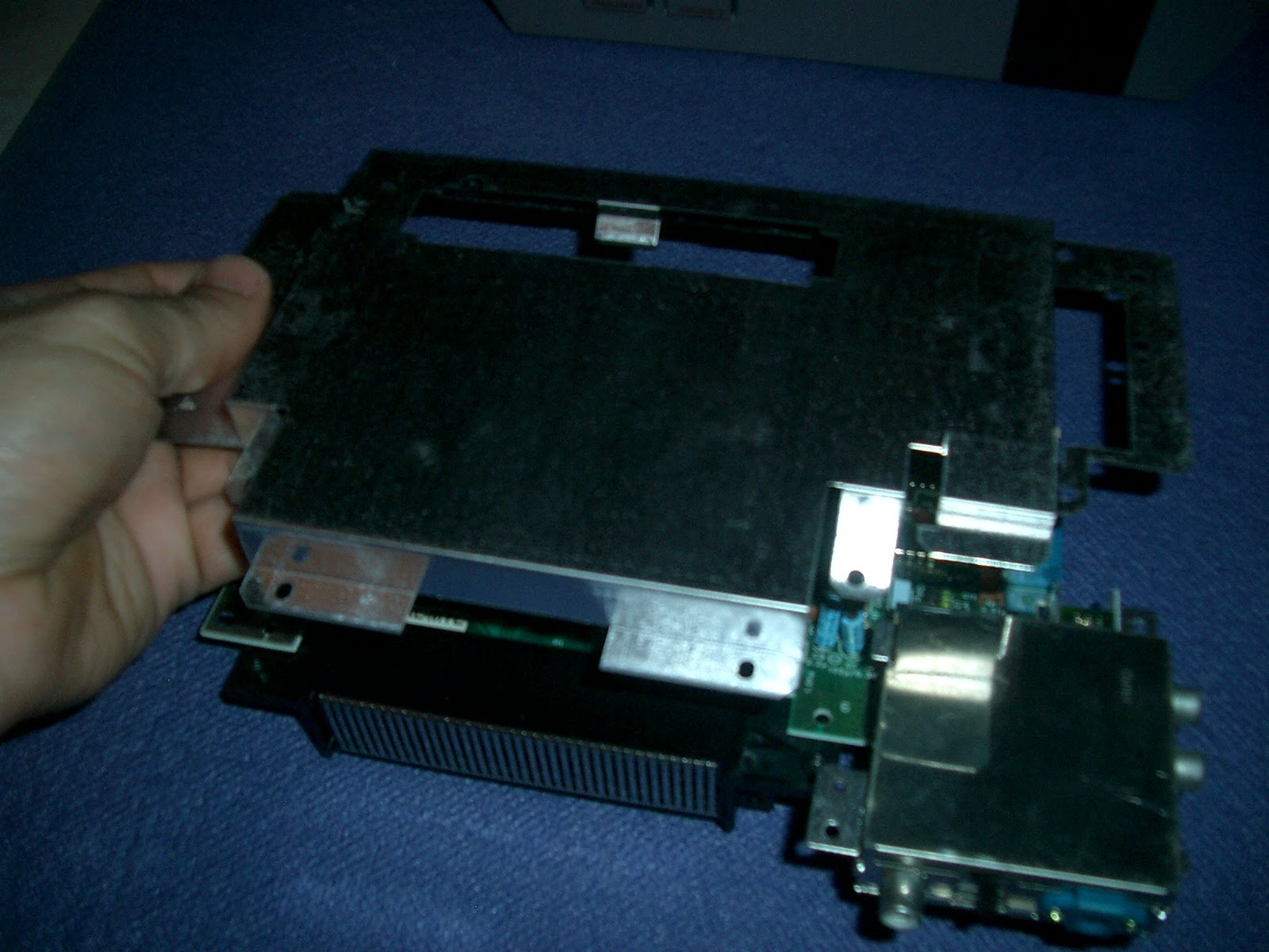
PASSO 9
Sfilare il telaietto inferiore per accedere agevolemente al connettore 72 pin.
Remove the lower frame for an easy access to 72-pin connector.


PASSO 10
Sfilare il connettore 72 pin.
Remove the 72 pin connector.


PASSO 11
Molto probabilmente il connettore della scheda madre sarà ossidato o sporco.
Probably the connector on the motherboard will be oxidized or dirty.

PASSO 12
Pulire, con delicatezza senza rovinare i contatti, utilizzando un panno appropiato che non lasci residui e lo spray apposito per contatti (silicon spray), il connettore della scheda madre fino ad ottenere un risultato simile a quello mostrato in figura.
Clean, gently, without damaging the contacts, using an appropiate cleaning drape and a specific electronic cleaning spray the connector on the motherboard to obtain a result similar to that shown.

PASSO 13
Prendere il connetore 72 pin nuovo.
Take the new 72-pin Connector.

PASSO 14
Inserire il nuovo connettore 72 pin sulla scheda madre.
Insert the new 72-pin connector on the motherboard.

PASSO 15
Posizionare il telaietto inferiore.
Place the bottom frame.
PASSO 16
Collegare i connettori precedentemente scollegati.
Connect the connectors were disconnected.
PASSO 17
Ribaltare la scheda madre ed inserirla in sede, come mostrato in figura.
Turn over the motherboard and put it in place, as shown in the figure.
PASSO 18
Serrare le due viti di fissaggio indicate in figura.
Tighten the two screws shown in figure.
PASSO 19
Inserire il carrello cartuccia nel connettore 72 pin e incastrare il labbro inferiore del carrello sotto la scheda madre.
Insert the tray into the new 72-pin connector and make attention to snap the lower lip of the tray under the motherboard.

PASSO 20
Operando su entrambi i lati avvitare moderatamente le tre viti di fissaggio indicate in figura, ricordandosi delle diverse lunghezze delle viti.
Man mano che si avvita provare il meccanismo del carrello cartuccia e serrare fino a quando si ottiene un perfetto funzionamento di incastro del carrello.
Working on both sides moderately screw the three screws shown in the figure, mindful of the different lengths of screws.
try the mechanism of the tray and continue to screw until you get a perfect joint operation of the tray mechanism.
PASSO 21
Posizionare il coperchietto superiore.
Position the upper cover.
PASSO 22
Serrare le sette viti di fissaggio coperchietto indicate in figura.
Tighten the seven cover mounting screws shown in the figure.
PASSO 23
Posizionare la base inferiore completa sul coperchio console.
Place the base on the console cover.
PASSO 24
Serrare le sei viti indicate in figura
Tighten the six screws shown in figure
;)
Il Nes è una console storica e a mio avviso fantastica!
Io lo uso tutt'oggi nonostante abbia praticamente la mia età, e non mi ha mai tradito...
L'unica cosa che capita sporadicamente è il fenomeno del blinking...cioè che vi lampeggia la lucina rossa all'accensione e che quindi non vi partono i giochi.
La soluzione consiste nel sostiruire il connettore a 72 pin perchè un pò con la sporcizia e un pò con il tempo si ossida innescando malfunzionamenti nella lettura della cartuccia inserita.
Qui di seguito proverò ad illustrarvi con una piccola guida come sostituire il connettore 72 pin con uno nuovo (facilmente reperibili sulla baia ;)) e anche come pulire il connettore sulla scheda madre (se sostituite solo il connettore 72 pin fate un lavoro a metà ;) ).
The NES console is a fantastic historical and in my opinion!
I use it so far despite having almost my age, and I have never betrayed ...
The only thing that happens occasionally is the blinking problem.
The solution is to excange the old 72-pin connector with one new beacuse the old connector is dirty and maybe a bit oxidizes triggering malfunctions in the reading of the cartridge inserted.
Below I will try to explain with a little guide how to replace the 72-pin connector with one new (you can found it easily on ebay;)) and also how to clean the connector on the motherboard (if you replace the 72 pin connector only you'll do just an half job; )).
Gli oggetti necessari per questa piccola riparazione sono davvero pochi:
The necessary objects for this small repairs are very few:
- Connettore 72 pin nuovo (72 pins connector replacement)
- Cacciavite a stella (screwdriver)
- Spray apposito per contatti elettrici (electronic cleaner spray)
- Panno che non lasci peluzzi appropiate cleaning drape
ATTENZIONE: La sostituzione del connettore a 72 pin è molto semplice e veloce e non richiede lo smontaggio della scheda madre del NES.
Ritengo però utile una volta che si sostituisce il connettore a 72 pin con uno nuovo, pulire accuratamente anche il connettore presente sulla scheda madre e per questo motivo, nel tutorial, ho illustrato anche come smontare la scheda per agevolare le operazioni di pulizia durante la sostituzione del connettore 72pin.
CAUTION: The replacement of the 72-pin connector is very simple and fast and does not require dismantling of the NES motherboard.
But I do feel good once you replace the 72-pin connector with a new, clean also the connector on the motherboard and that is why, in the tutorial, I also explained how to disassemble the motherboard from the console to facilitate cleaning when changing the 72pin connector.
PASSO 1
Operando sul lato inferiore del Nes, svitare e togliere le sei viti di fissaggio indicate in figura.
Working from the bottom of the Nes, unscrew and remove the six screws shown in the figure.

PASSO 2
Separare la base dal coperchio superiore e appoggiarla su un piano per agevolare le operazioni.
Separate base and top cover and place the base on a plan to facilitate the operations.

PASSO 3
Svitare e togliere le sette viti di fissaggio indicate in figura.
Unscrew and remove the seven screws shown in the figure.

PASSO 4
Rimuovere il coperchio.
Remove the cover.

PASSO 5
Operando su entrambi i lati, svitare e togliere le tre viti di fissaggio (due corte ed una lunga per lato).
Working on both sides, unscrew and remove the three screws (two short and one long per side).


PASSO 6
Sfilare il carrello cartuccia
Remove the cartridge tray.

PASSO 7
Svitare e togliere le due viti di fissaggio indicate in figura.
Unscrew and remove the two screws shown in the figure.

PASSO 8
Sollevare e ribaltare la scheda madre e scollegare i connettori indicati in figura.
Lift and turn the motherboard and disconnect the connectors indicated in the figure.


PASSO 9
Sfilare il telaietto inferiore per accedere agevolemente al connettore 72 pin.
Remove the lower frame for an easy access to 72-pin connector.

PASSO 10
Sfilare il connettore 72 pin.
Remove the 72 pin connector.


PASSO 11
Molto probabilmente il connettore della scheda madre sarà ossidato o sporco.
Probably the connector on the motherboard will be oxidized or dirty.

PASSO 12
Pulire, con delicatezza senza rovinare i contatti, utilizzando un panno appropiato che non lasci residui e lo spray apposito per contatti (silicon spray), il connettore della scheda madre fino ad ottenere un risultato simile a quello mostrato in figura.
Clean, gently, without damaging the contacts, using an appropiate cleaning drape and a specific electronic cleaning spray the connector on the motherboard to obtain a result similar to that shown.

PASSO 13
Prendere il connetore 72 pin nuovo.
Take the new 72-pin Connector.

PASSO 14
Inserire il nuovo connettore 72 pin sulla scheda madre.
Insert the new 72-pin connector on the motherboard.

PASSO 15
Posizionare il telaietto inferiore.
Place the bottom frame.
PASSO 16
Collegare i connettori precedentemente scollegati.
Connect the connectors were disconnected.
PASSO 17
Ribaltare la scheda madre ed inserirla in sede, come mostrato in figura.
Turn over the motherboard and put it in place, as shown in the figure.
PASSO 18
Serrare le due viti di fissaggio indicate in figura.
Tighten the two screws shown in figure.
PASSO 19
Inserire il carrello cartuccia nel connettore 72 pin e incastrare il labbro inferiore del carrello sotto la scheda madre.
Insert the tray into the new 72-pin connector and make attention to snap the lower lip of the tray under the motherboard.

PASSO 20
Operando su entrambi i lati avvitare moderatamente le tre viti di fissaggio indicate in figura, ricordandosi delle diverse lunghezze delle viti.
Man mano che si avvita provare il meccanismo del carrello cartuccia e serrare fino a quando si ottiene un perfetto funzionamento di incastro del carrello.
Working on both sides moderately screw the three screws shown in the figure, mindful of the different lengths of screws.
try the mechanism of the tray and continue to screw until you get a perfect joint operation of the tray mechanism.
PASSO 21
Posizionare il coperchietto superiore.
Position the upper cover.
PASSO 22
Serrare le sette viti di fissaggio coperchietto indicate in figura.
Tighten the seven cover mounting screws shown in the figure.
PASSO 23
Posizionare la base inferiore completa sul coperchio console.
Place the base on the console cover.
PASSO 24
Serrare le sei viti indicate in figura
Tighten the six screws shown in figure
;)
Ottimo lavoro!
RispondiEliminaGrazie mille Fede ;)
RispondiElimina